 |
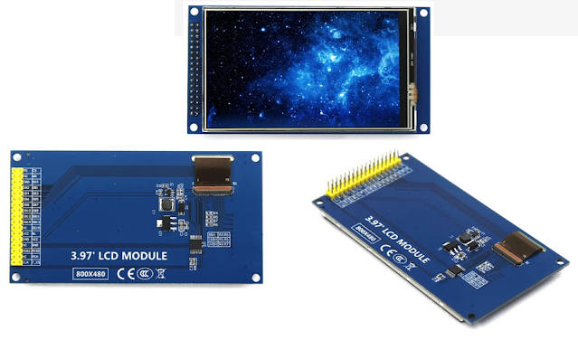
Figure 1 - 4" TFT display
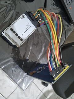
This article shows how to connect Arduino Mega and the TFT display from Figure 1. Mega output pins are 5V while the display input/output pins are 3.3V. So its necessary to use a 5 to 3.3V level converter (Figure 2) or LCD shield (Figure 3).
Data are transfered by 16-bit or 8-bit wires and it is easy to get confused in the sea of jumpers. 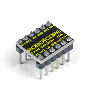 | | Figure 2 - Level converter |
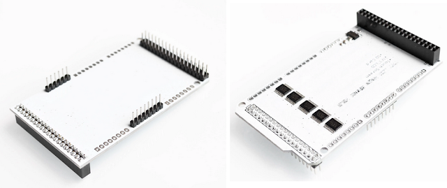 | Figure 3 - LCD shield used in this article
|
|
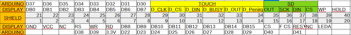 |
| Figure 4 - Connections between arduino, shield and lcd display |
Place the LCD shield into Mega in the digital output pins that goes from 20 to 52.
Make the connections depicted in Figure 4 using jumpers. That is, pin 1 from shield goes to pin GND in TFT display, pin 2 goes to VCC, pin 3 goes to not connected, pin 4 to RS, and so on. Figure 5 shows the result.
 |
| Figure 5 - Connection between LCD shield and 4" display |
Download the library from the link below, unzip and place it in the Arduino libraries folder.
https://github.com/evrttn/4.0inch-display
.png) |
| Figure 6 - Code to be uploaded into Mega |
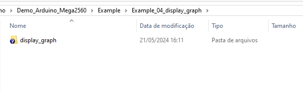
Go to folder 1-Demo\Demo_Arduino_Mega2560\Example\Example_04_display_graph\display_graph and upload display_graph.ino. If all goes right, the result would be like Figure 7.
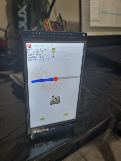 |
| Figure 7 - Display Graph demo |
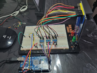
If you are crazy enough (as me) to use level converters, be prepared to be lost in messy web of jumpers. See Figure 8.
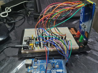 |
| Figure 8 - 16 bit using logic level. |
But things go better in 8-bit. To do so, you must solder R2 connections in the back of the display and also disconnect R3. Then, go to 1-Demo\Demo_Arduino_Mega2560\Install libraries\LCDWIKI_KBV and change CONFIG_USE_8BIT_BUS constant from 0 to 1 in lcd_mode.h
 |
| Figure 9 - 8 bit using logic level. |
Thanks for coming.


.png)


Comentários
Postar um comentário